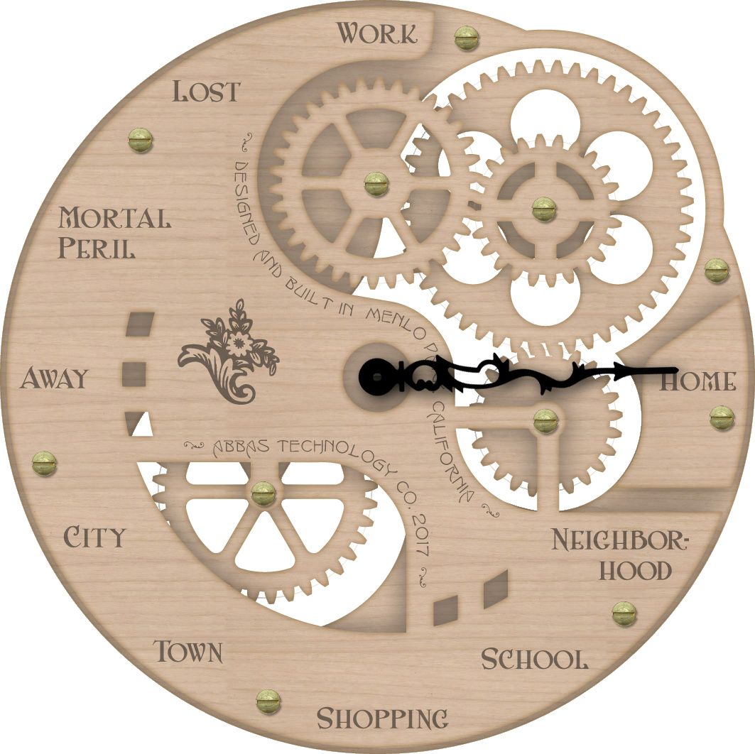
My family often wants to know where I am and when I’ll be home for dinner. To keep them in-the-know, I built a home appliance I call the “Gnomon”. It hangs on the dining room wall and shows them where I am. (Click on the pictures for a larger version.)
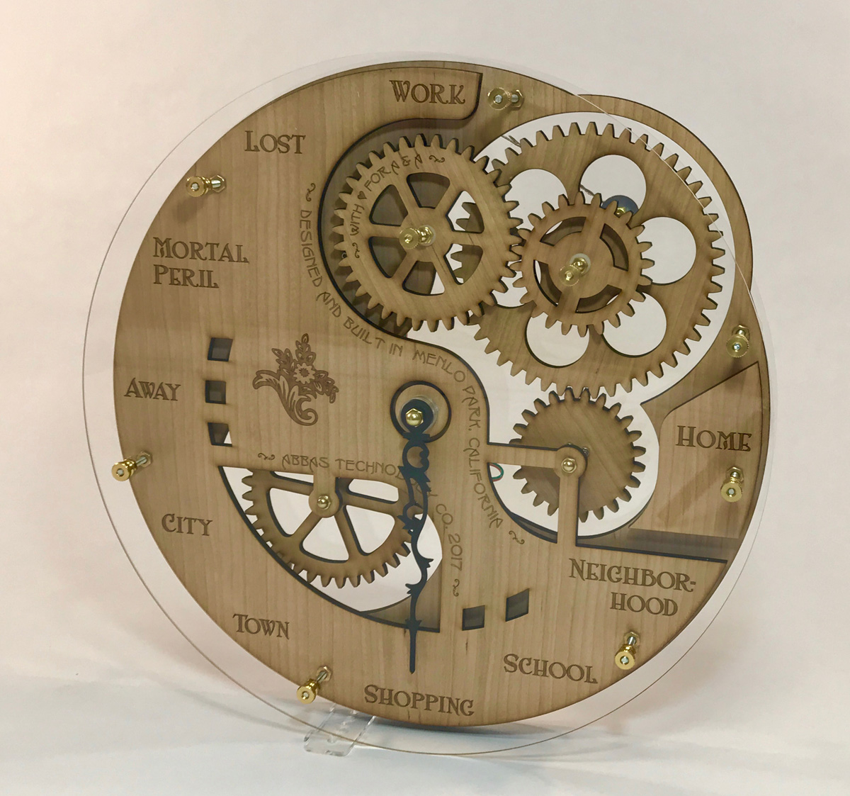
It's about 15 inches in diameter. Here’s a movie so you can see it in action. This is “demo mode” (because otherwise it only moves when I go somewhere).
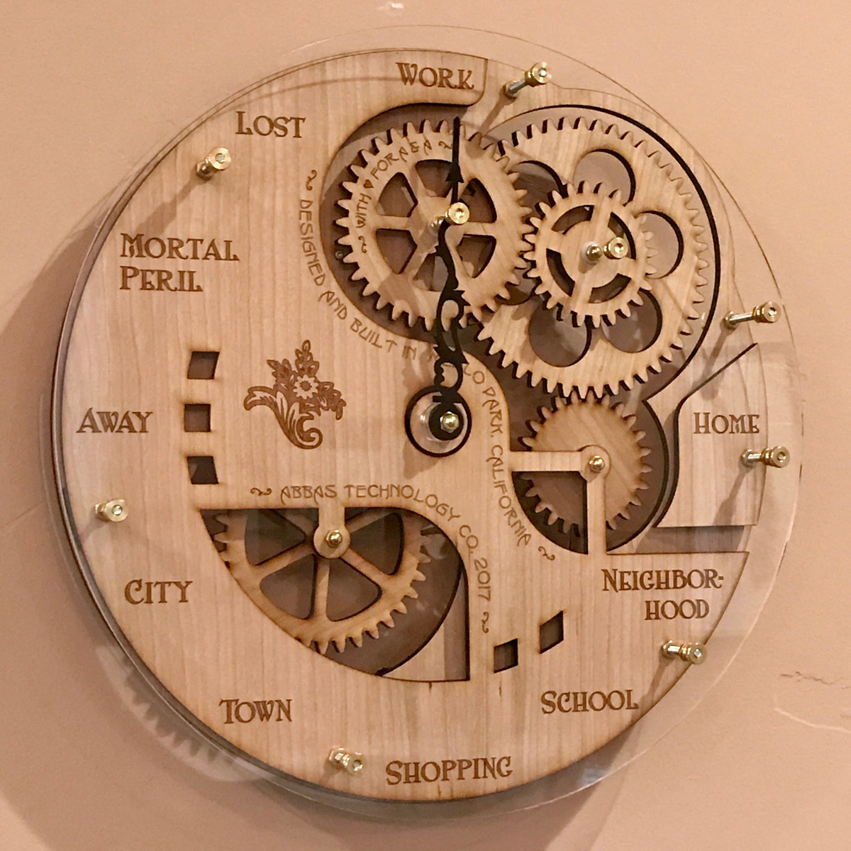
It looks a little like a clock, but there’s only one hand (the black one that’s pointing down in the picture). As I go about my day, the hand turns to point to “work”, “home”, “neighborhood”, and so on depending on where I happen to be. For fun, the gears turn too — the one in the lower left turns with the hand, but the ones in the upper right spin depending on how fast I’m moving and whether I’m going towards or away from home. (How does it know where I am? My iPhone.)
For those of you familiar with Harry Potter, you’ll no doubt recognize my inspiration. J. K. Rowling put a clock in the Weasleys’ house that has hands for each member of the family to tell where they are and what they’re up to. The Gnomon isn’t the first time someone has tried to recreate this magic in real life (Pat Peters, Trey Bagley) but I wasn’t interested in trying to make something similar to the version in the movies, I wanted a novel design (no pun intended).
Construction
I wanted an “Arts & Crafts”-era look... I’m no art historian but I guess what I was shooting for was some combination of Art Nouveau, steampunk, and Art Deco. For that, the Gnomon needed gears. I don’t know how to make a metal gearbox but I had seen wooden gears at the Maker Faire in San Mateo so I decided to give that a try. I don’t have a big workshop and I’m not a member of a maker space, so cutting the gears myself seemed too ambitious. But there’s an online laser-cutting service called Ponoko — you can make a design in Adobe Illustrator, upload it as an EPS, and they’ll send you the physical product in the mail. They have a big variety of materials, so I decided to use clear acrylic for an enclosure and MDF for the face & works.
The gears posed a particular challenge: how do you design gears in a shape that allows them to mesh and turn smoothly? Luckily (for someone who didn’t major in mechanical engineering) I found Abel Vincze’s awesome Gear Generator tool. Apparently what I needed were “involute spur gears”, which Gear Generator will help you design.
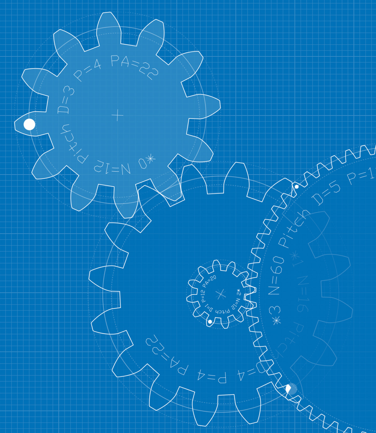
Download the gear design from Gear Generator as an SVG file, import it into Illustrator, and voilà. My Illustrator design drawing ended up looking like this:
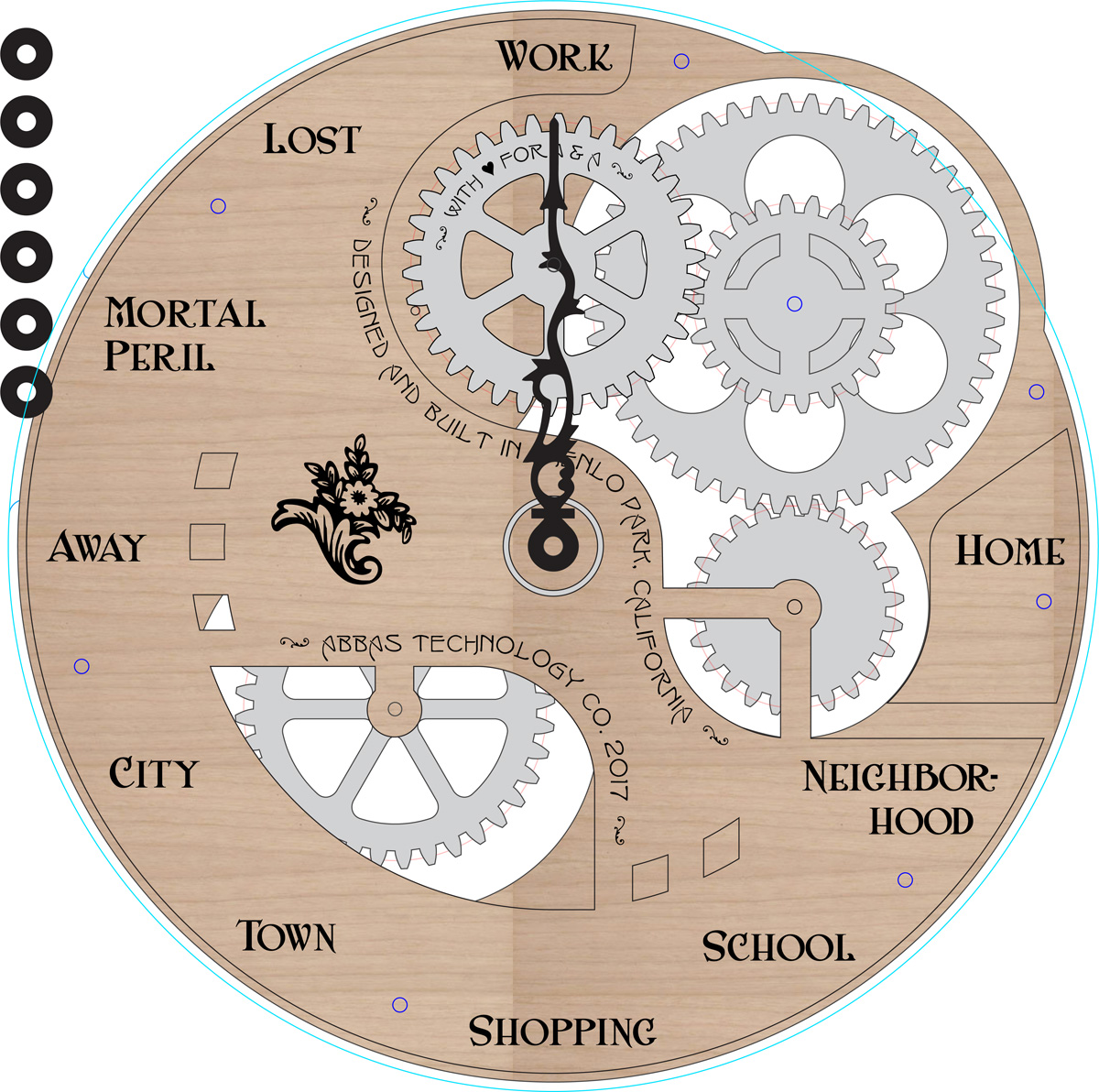
... with all the parts (back acrylic, back MDF, gears, front MDF, labels, annotations, flower decoration, hand, front acrylic, etc) separated into a lot of different layers. To check the look, I made a low fidelity “render” by importing the layers into Photoshop and adding some drop shadows.
Yep, that’s what I was picturing.
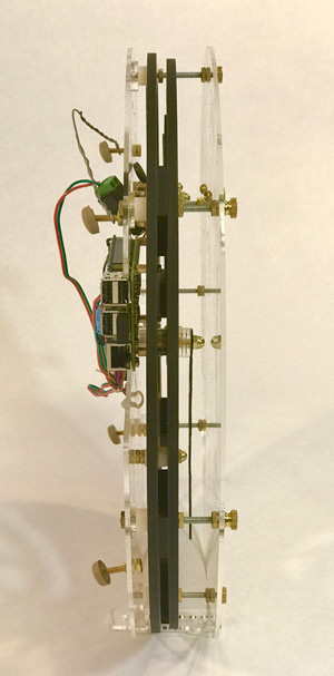
Behind the scenes, it’s electronic of course. I chose a Raspberry Pi 2 Model B to hide in the back, with a wifi dongle and two small stepper motors.
The next step was to separate my design drawing into patterns that Ponoko could use to laser-cut the materials. Two for the clear acrylic, two for the MDF, and one for the thin black acrylic hand:
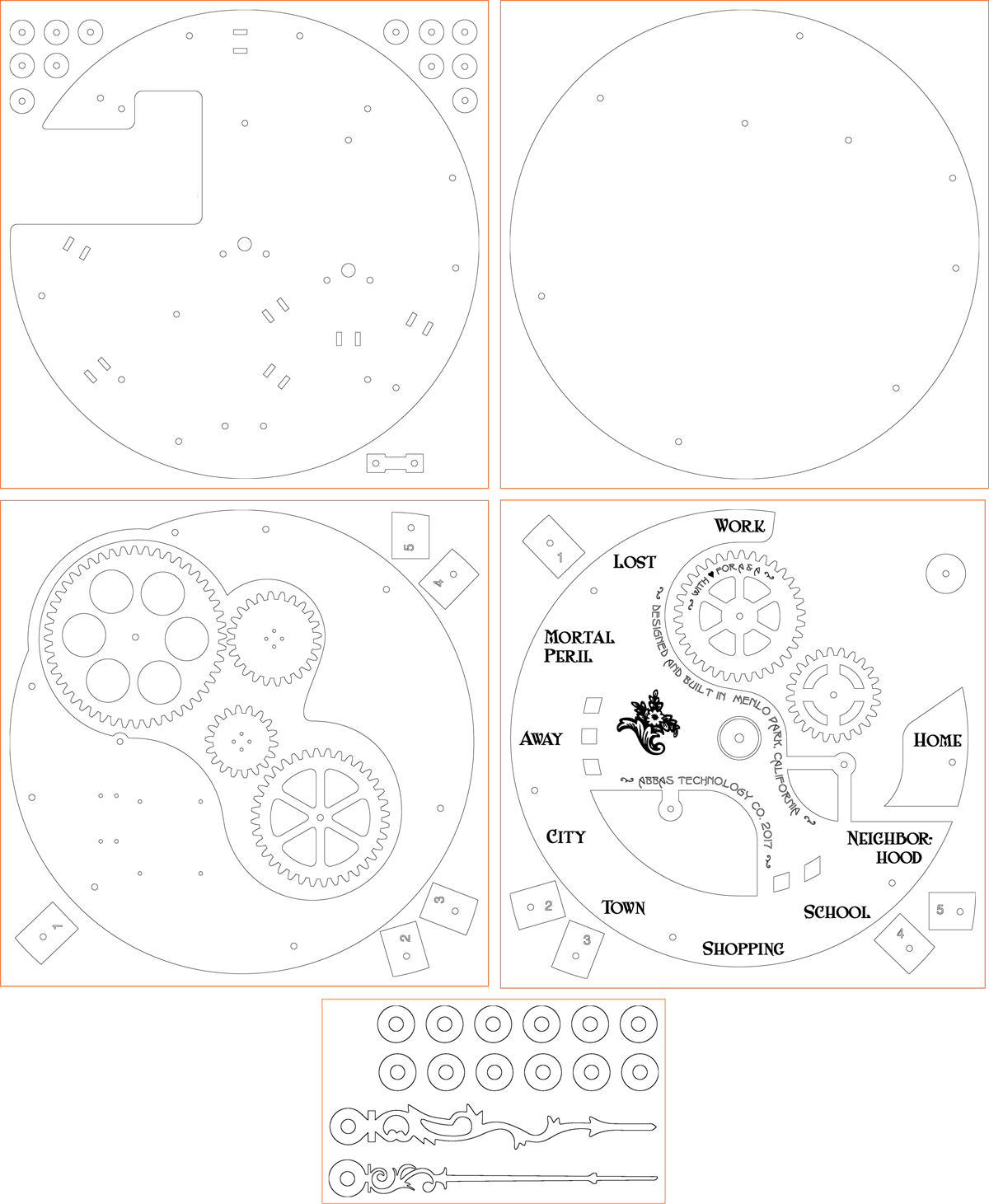
There are a couple of details there that deserve some explanation.
- On the back acrylic sheet, I made some washers because I wanted to use them as spacers. They help separate the back acrylic from the back MDF, and I also ended up using a few of them as spacers to get the hand to just the right height. The big L-shaped cut out is for the Raspberry Pi and for a capacitive touch adapter that I’m considering adding but haven’t hooked up yet. There are holes around the edge for the rods that hold the whole thing together, rods that hold the three free-spinning gears, stepper motor shafts, stepper motor mounting screws, four machine screw “legs” to hold the device away from the wall, and slots to hold zip-ties that’ll help hold wires in place and keep them hidden.
- The front sheet is pretty simple, it only has holes for the edge rods and two of the gear axles. The gear-axle holes were a mistake actually... I obviously can’t put axles all the way from the back acrylic to the front because then the hand wouldn’t be able to turn! But it turned out okay because I just put short machine screws with knurled nuts through those two holes in the front, and even though they’re completely non-functional it looks like I meant to do it that way.
- The back MDF has holes for the edge rods, and also some holes for the M2.5 mounting screws that hold the Raspberry Pi. The little blocks around the edge were to go behind this layer as standoffs, but I ended up not needing them.
- The front MDF has more standoff blocks, which I did use to between this layer and the back MDF. I put numbers on them so I could keep track of them because they’re shaped similarly (but they’re not identical). The text was all done in a different color so that Ponoko would know to just etch the surface, not cut all the way through. The washer up in the corner was for the central axle, but I ended up not needing it.
- On the black acrylic, I made some more washers but I didn’t end up using them for anything. I cut two different hand designs because I wasn’t sure which one I would end up liking better.
A week after submitting my design to Ponoko, the finished pieces showed up on my doorstep, and I have to say it’s pretty amazing to see my drawings magically turn into physical reality. (Having a week of anticipation probably amplified this feeling.)
To assemble the pieces, I used mostly #8-32 threaded rods with brass hex nuts, acorn nuts, and knurled nuts. The local Ace Hardware stores do a great job stocking a variety of hardware, without which this project would’ve been much harder. My decision to use threaded rods as axles was probably questionable, but adding some flanged nylon spacers as bearings helped to keep the gears from climbing the threads. I also had to use hex nuts in pairs sometimes to make sure turning gears didn’t rotate any nuts. Here’s the kind of hardware I used:
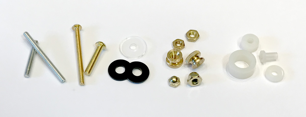
I didn’t allow any gaps in my gear design, so if the gears ever get too close to each other then they bind (stop turning). Luckily, the holes I put in the acrylic were a little too big and that afforded me the opportunity to adjust the spacing of the gears a little and keep everything turning freely. That took some trial and error.
Electronics
Because Adafruit makes an awesome DC+Stepper Motor HAT for Raspberry Pi, hooking my microcontroller up to the stepper motors was super-easy. I just soldered the kit together and plugged the motor wires into the hat’s terminal block. The biggest wrinkle is that people recommend a separate power supply for the motors because the RPi doesn’t like it if its supply voltage dips, but I didn’t feel like running cables from two separate wall transformers. So instead of two whole power supplies, I went over to Polulu to buy a S7V7F5 voltage regulator to help keep the RPi’s supply at 5V even if the steppers draw a lot of current for a moment. I stuck an electrolytic capacitor in there too just for good measure. So far I haven’t had any stability problems.
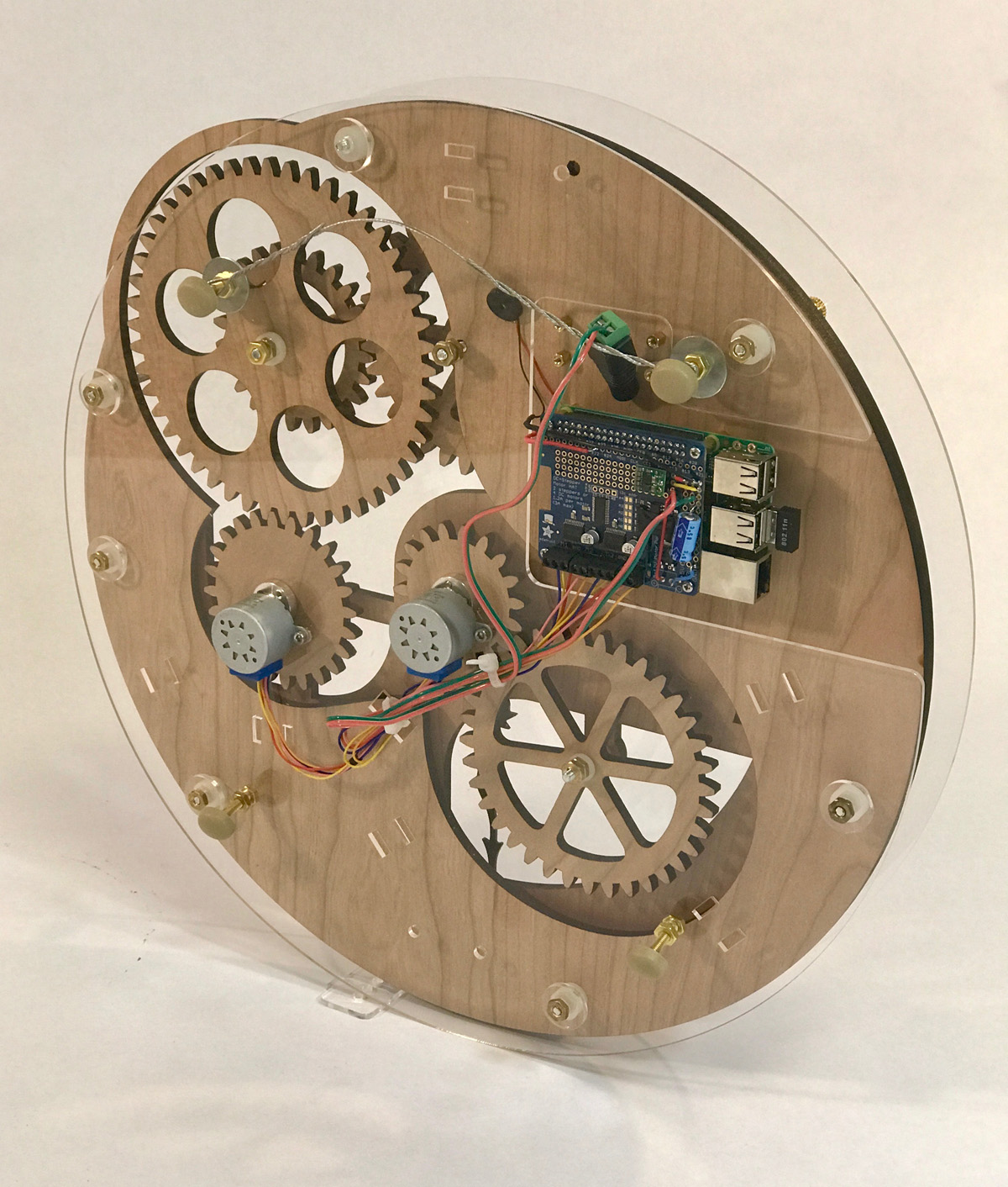
If you look closely at the back you might notice that I also hooked up a tiny piezo for audio feedback (beeps and such). It’s so quiet it’s almost inaudible though, so I don’t know if it’ll be good for anything.
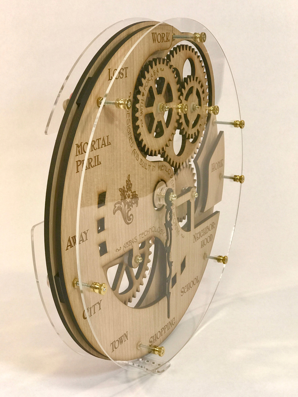
I hid the power cord by running it through the wall, and covered up the LEDs with tape to help preserve the illusion. Here’s how it looks on the wall.
Software
To make the hand actually do something intelligent, there are a few pieces required:
- An app on my iPhone that sends my location to a server
- A program on a server that translates those location messages into instructions for where the hand should move
- A program on the Raspberry Pi that drives the stepper motors appropriately.
When I build a distributed system that needs to communicate across a network, my usual modus operandi is to use either a custom line-oriented protocol on a TCP connection, or REST (HTTP). But recently I learned of MQTT and that seemed like a really good fit for this project. For that I need a message broker, and Mosquitto seemed to be a popular choice so I installed that on my Ubuntu box. For the iPhone app, at first I figured I’d write my own but then I discovered OwnTracks that seemed to fit the bill nicely so I went with that. It’s easy to set up and works well.
To drive the motors, luckily Adafruit provides a very handy Python library to drive their motor hat. It supports four different patterns for driving the motor coils: from slowest to fastest they’re “microstep”, “interleave”, “single”, and “double”. I found single and double to be too noisy, and although microstep provides very smooth motion it also causes the motor to emit a high-pitched whine. Interleave was the quietest so I used that.
After some experimentation I found the stepper positions that point to each of my ten labels, but I also discovered that the hand movement lags about 7 degrees when the motor switches directions. So it took a little bit of extra programming to take that into account and move the hand to exactly the right spot regardless of which direction it’s rotating, by “over-rotating” by 3.5 degrees.
For mapping locations to hand positions, I’ve wrote a Python script that runs on the Gnomon and subscribes to MQTT messages using paho-mqtt. It extracts the latitude and longitude attributes from message data (JSON) and compares them to a list of circular geographic regions (home, office, etc) in order to generate hand positions.
Questions or comments? Email me at .
2017 September 2